
This year for Christmas my Dad bought me a single present, the March Pump I had been wanting for quite a while now. Since I don't have a brew stand and have to tear down and move my brew house after every brewday the best option for my needs is to build it into a tool box. I happened to have a tool box fit for the job as well. I looked at the BYO article for the build as well as a few others and made a couple tweeks. One tweek I added is to include an outlet along with the switch so that I can plug in other electrical equipment when needed like my aquarium pump for aerating my wort pre-fermentation. I also went with a flat light switch instead of the standard one that sticks out away from the surface, this will keep me from possibly catching something on it and accidentally turning it on while dry.
Tools:
1" Hole Saw
Cordless Drill
11/64" Drill Bit
3/4" Drill Bit
Hand Held Jig Saw
Wire Cutters
Wire Stripper
Flathead Screwdriver
Phillips Screwdriver
Housing & Wiring Parts:
March Pump
10' Extension Cord
Tool Box
GFCI Outlet (black)
Flat Light Switch (black)
Dual Electical Box
Dual Switch Face Plate (black)
2"X6"X6" Wooden Block
Small length of Wood Lathe (Glued to wooden block)
(2) 1/2" Wood Screws
(8) 8/32"X3/4" SS Bolt
(4) 8/32" Hex Nuts
(2) Plastic stick-on wall hangers
Pump Head Parts:
Teflon Tape
(2) Brass 1/2" X 1/2" FPT 90' Elbow
(1) Brass 1/2" MPT to 1/2" FPT Ball Valve
(2) Brass 1/2" MPT to Quick Disconnect (I used Aluminum Camlocks)
Tool Box Build
Step 1:
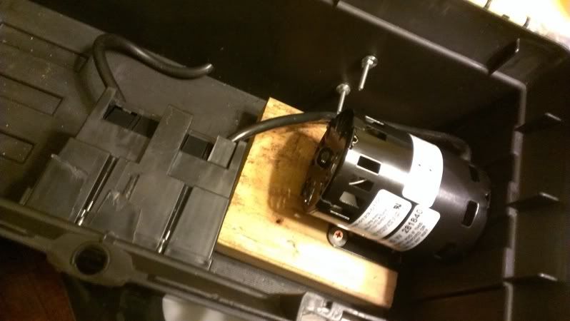
Remove the 4 screws that hold the pump head to the housing. Next remove the 4 screws that attach the housing to the pump motor. Use the 1/2" wood screws to fasten the pump motor to the 2X6 block making sure that the motor is just past the edge of the block so that it will be able to pull flush to the tool box edge. When I made mine I used only the 2X6 and once completing the pump head it is just a little too tall for the tool box to fit flush on the ground. The lathe helps to give a little more height to allow it to sit flush.
Step 2:
Measure where the pump head will fit through on one side of the tool box. Do the same with the dual electrical box (trace the box on the front edge with a pencil, then redraw it 1/8" smaller on all sides). Use the 11/64" drill bit to drill a hole in each corner of the electric box area and in the middle of the pump head area. Attach the hole saw to the electric drill and cut out the hole for the pump head. Next detach the Jig Saw blade and insert it through one of the holes in the front. Retach the blade and cut out the inner box area. Use the 3/4" drill bit to drill a hole in the back of the box in the middle near the bottom for the cord.

Step 3:
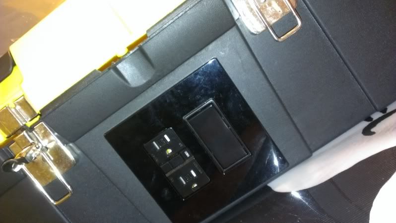
Cut the female end of the extension cord off and strip away 4" of the outer covering. Fit the cord through the hole in the back and into the electrical box on the inside of the tool box, as well as the cord from the pump. Attach the wiring to the GFCI outlet and switch according to the diagram above (use some of the extra wire from the cord for the pump since there will be quite a bit more than you will need to for the tight quarters of the tool box). After wiring the GFCI and Switch with the wires from the power cord and pump, fit the outlet and switch through the box hole on the front leaving the electrical box and wires inside the tool box. Use the bolts that come with the outlet and switch to attach them to the electric box on the inside. Next attach the plate cover to finish off the outlet and switch.
Step 4:
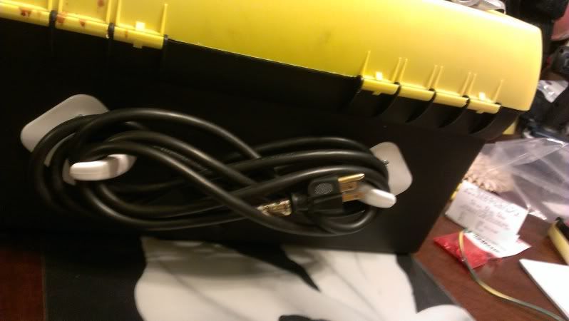
Align the stick on coat hangers on the back of the tool box so that the balance of the power cord can be wrapped around the hooks for storage. Remove the backing on the stickers and apply pressure so that they stick. Using the 11'64" drill 2 holes through the hangers and the wall of the tool box. Insert a 8/32" bolt through each hole and attach with the 8/24" machine nuts from the inside; tighten down. Now you can wrap the cord onto the back of the tool box. Another alternative if you didn't want to use the remaining space in the tool box for tools and such you could drill out a hole near the top of the tool box on the side adjacent the pump and use the jigsaw to cut out the remainder allowing the cord to be stored inside the box and draped through the hole when needed for use.
Step 5:
Align your pump inside the tool box with the magnetic head fitted through the hole in the side you drilled for it. Drill 4 holes around the hole aligned with the 4 holes in the motor housing for the screws to reattach the pump housing. Once you have these holes drilled and aligned, slide the housing over the magnetic head on the outside of the tool box, and attach to the motor on the inside of the box using 4 of the 8/32" X 3/4" bolts (the original bolts are too short to fit through the added depth of the tool box).
Pump Head Build
There are different configurations for building out your pump head. You can go with a side to side or an up and down. Many people go with the up and down since it is supposed to be the best for priming the pump, and is the set up I went with. Some go with a T split on top with 2 ball valves, one for the fluid and one for venting any air in the line. I chose to go with the single ball valve on an elbow since any air in the line should simply escape up the tubing and out with the liquid.
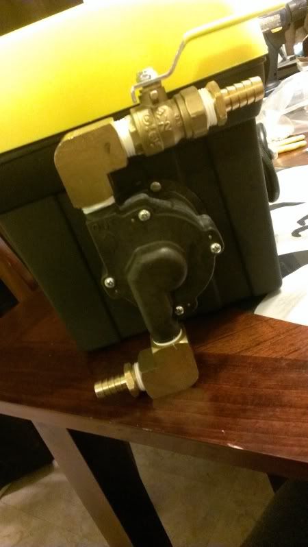
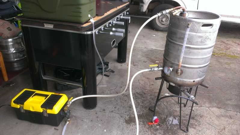
Also, some set ups call for hose barbs for the inlet and outlet (as in the picture below), I used this set up once and immediately got camlock quick disconnects for them instead. The barb and hose clamp option is much more difficult to remove and dry/store after use.
Also, some set ups call for hose barbs for the inlet and outlet (as in the picture below), I used this set up once and immediately got camlock quick disconnects for them instead. The barb and hose clamp option is much more difficult to remove and dry/store after use.
Step 6:
Wrap both the inlet and outlet threading with Teflon Tape. Attach one of the elbows to the inlet thread until it is tight and faces to the left when attached to the pump housing. Next wrap the thread on one of the quick disconnects with Teflon Tape and thread it into the other end of the elbow. Once this is done you can now connect and release your tubing easily for storing and drying. Now you can attach the other elbow to the outlet end of the pump head so that it is tight and facing right. Wrap the female threads on the ball valve and thread it into the elbow until tight and straightened with the ball valve handle facing right when opened and aligned on top. Next wrap the threads on the second quick connect and tighten it into the ball valve.
Step 7:
Align the pump head to the housing and attach it using the original screws. To ensure that everything is in working order, attach your inlet hosing to a water source and allow the tubing to fill (never run a March Pump when dry). Open the ball valve, plug in the pump, turn on the switch and see what happens. For my hosing I used a 1 foot section of 1/2" ID silicone tubing at the inlet, and attached a length of my Thermoplastic tubing to it using a 1/2" Barb to MPT and a 1/2" Barb to FPT, with my camlock on the end of the thermoplastic tubing. This allows me to see the liquid in the tubing at the inlet to ensure that I am not running it dry (thermoplastic tubing is completely opaque).
No comments:
Post a Comment