
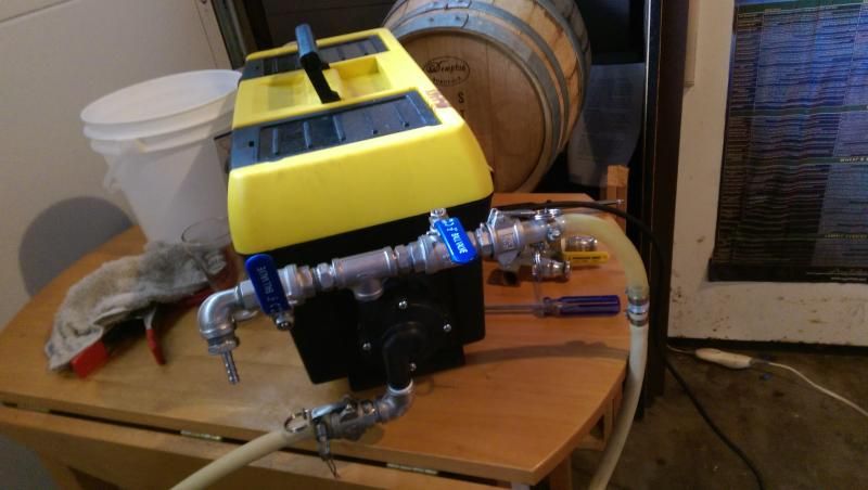
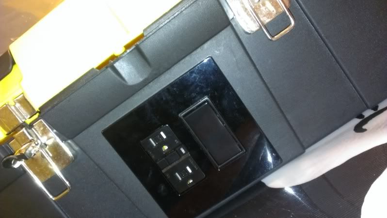
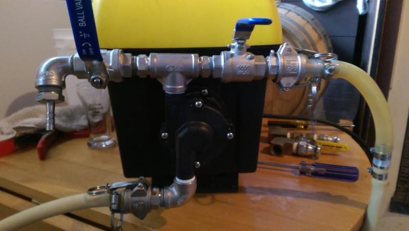
2 years ago for Christmas my Dad bought me a single present, the March Pump I had been wanting for quite a while. Since I don't have a brew stand and have to tear down and move my brew house after every brewday the best option for my needs was to build it into a tool box. I happened to have a tool box fit for the job as well. Originally I had looked at BYO articles for the build, as well as a few others. I opted to include an outlet along with the switch so that I can plug in other electrical equipment when needed like my vacuum sealer for resealing hops. I also went with a flat light switch instead of the standard one that sticks out away from the surface, this will keep me from possibly catching something on it and accidentally turning it on while dry.
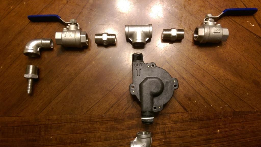
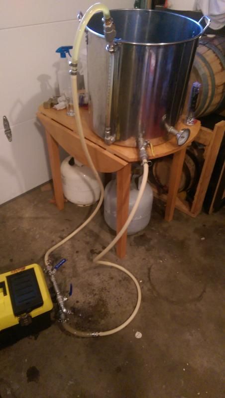
After a few years of using the original mixture of brass fittings with the aluminum camlocks I finally switched to all Stainless Steel. This gives me the ability to know that there isn't any reacting of the metals, and allows me to use any SS safe cleaners with out worrying if that cleaner is safe for multiple metals. And lets just be honest, the full SS looks sexier. I scored SS cam locks for my birthday gift from my wife, and had some bonuses from work that allowed me to source the other pieces on eBay for a good deal. On this iteration I also added a second ball valve on the out flow for bleeding off air and for pulling samples (thanks to the recent BYO article for giving me more info on this).
To make it easier on anyone wanting to build there own, I have included the original build of the pump into the tool box, and then updated the install of the fittings onto the pump head.
Tools:
1" Hole Saw
Cordless Drill
11/64" Drill Bit
3/4" Drill Bit
Hand Held Jig Saw
Wire Cutters
Wire Stripper
Flathead Screwdriver
Phillips Screwdriver
Housing & Wiring Parts:
March Pump
10' Extension Cord
Tool Box
GFCI Outlet (black)
Flat Light Switch (black)
Dual Electical Box
Dual Switch Face Plate (black)
2"X6"X6" Wooden Block
Small length of Wood Lathe (Glued to wooden block)
(2) 1/2" Wood Screws
(8) 8/32"X3/4" SS Bolt
(4) 8/32" Hex Nuts
 (2) Plastic stick-on wall hangers
Stainless Steel Pump Head Parts:
Teflon Tape
(2) SS 1/2" X 1/2" FPT Ball Valve
(1) SS 1/2" MPT X 1/2" FPT Street Elbow
(1) SS 1/2" MPT X 1/4" Barb
(1) SS 1/2" MPT X 1/2" FPT Street Elbow
(1) SS 1/2" MPT X 1/4" Barb
Tool Box Build
Step 1:
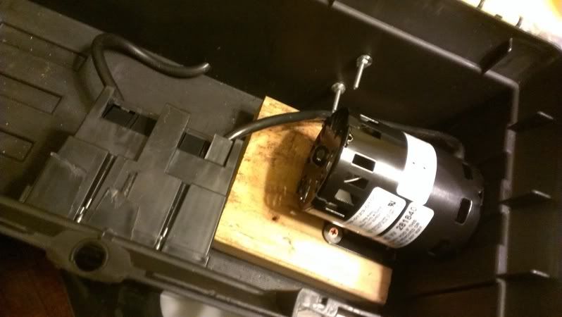
Remove the 4 screws that hold the pump head to the housing. Next remove the 4 screws that attach the housing to the pump motor. Use the 1/2" wood screws to fasten the pump motor to the 2X6 block making sure that the motor is just past the edge of the block so that it will be able to pull flush to the tool box edge. When I made mine I used only the 2X6 and once completing the pump head it is just a little too tall for the tool box to fit flush on the ground. The lathe helps to give a little more height to allow it to sit flush.
Step 2:
Measure where the pump head will fit through on one side of the tool box. Do the same with the dual electrical box (trace the box on the front edge with a pencil, then redraw it 1/8" smaller on all sides). Use the 11/64" drill bit to drill a hole in each corner of the electric box area and in the middle of the pump head area. Attach the hole saw to the electric drill and cut out the hole for the pump head. Next detach the Jig Saw blade and insert it through one of the holes in the front. Retach the blade and cut out the inner box area. Use the 3/4" drill bit to drill a hole in the back of the box in the middle near the bottom for the cord.

Step 3:
Cut the female end of the extension cord off and strip away 4" of the outer covering. Fit the cord through the hole in the back and into the electrical box on the inside of the tool box, as well as the cord from the pump. Attach the wiring to the GFCI outlet and switch according to the diagram above (use some of the extra wire from the cord for the pump since there will be quite a bit more than you will need to for the tight quarters of the tool box). After wiring the GFCI and Switch with the wires from the power cord and pump, fit the outlet and switch through the box hole on the front leaving the electrical box and wires inside the tool box. Use the bolts that come with the outlet and switch to attach them to the electric box on the inside. Next attach the plate cover to finish off the outlet and switch.
Step 4:
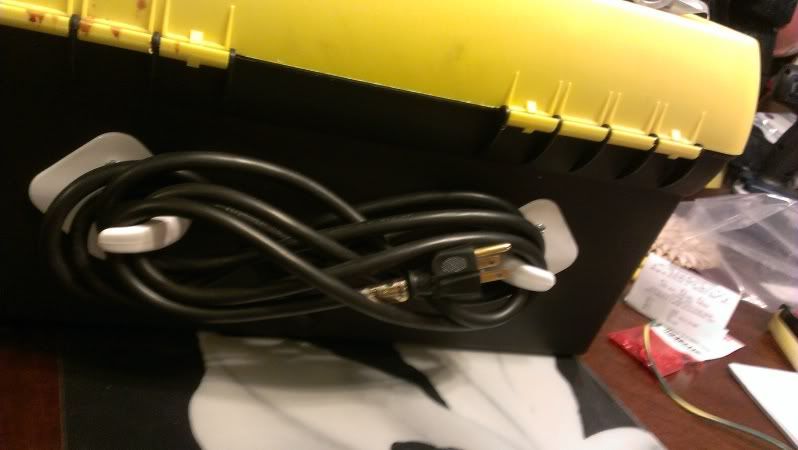
Align the stick on coat hangers on the back of the tool box so that the balance of the power cord can be wrapped around the hooks for storage. Remove the backing on the stickers and apply pressure so that they stick. Using the 11'64" drill 2 holes through the hangers and the wall of the tool box. Insert a 8/32" bolt through each hole and attach with the 8/24" machine nuts from the inside; tighten down. Now you can wrap the cord onto the back of the tool box. Another alternative if you didn't want to use the remaining space in the tool box for tools and such you could drill out a hole near the top of the tool box on the side adjacent the pump and use the jigsaw to cut out the remainder allowing the cord to be stored inside the box and draped through the hole when needed for use.
Step 5:
Align your pump inside the tool box with the magnetic head fitted through the hole in the side you drilled for it. Drill 4 holes around the hole aligned with the 4 holes in the motor housing for the screws to reattach the pump housing. Once you have these holes drilled and aligned, slide the housing over the magnetic head on the outside of the tool box, and attach to the motor on the inside of the box using 4 of the 8/32" X 3/4" bolts (the original bolts are too short to fit through the added depth of the tool box).
Pump Head Build
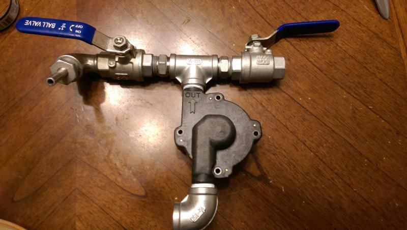
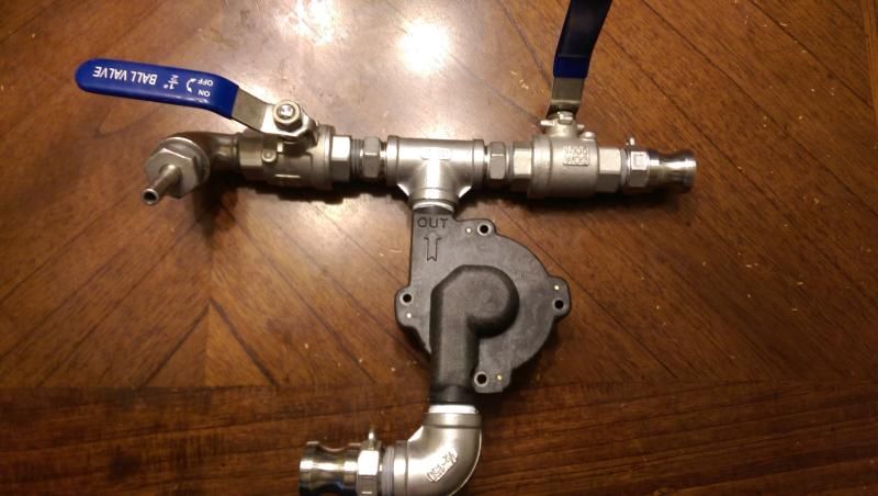
There are different configurations for building out your pump head. You can go with a side to side or an up and down. Many people go with the up and down since it is supposed to be the best for priming the pump, and is the set up I went with. I went with a T split on top with 2 ball valves, one for the fluid and one for venting any air in the line as well as for pulling samples. After using a pump with and without the T vent, I much prefer the vented.
Also, some set ups call for hose barbs for the inlet and outlet, I opted to go with cam lock quick disconnect fittings for ease of use. The barb and hose clamp option is much more difficult to remove and dry/store after use, and it wares on the tubing which is expensive.
Also, some set ups call for hose barbs for the inlet and outlet, I opted to go with cam lock quick disconnect fittings for ease of use. The barb and hose clamp option is much more difficult to remove and dry/store after use, and it wares on the tubing which is expensive.
Step 6:
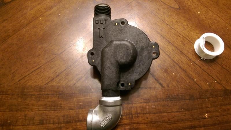
Wrap both the inlet and outlet threading with Teflon Tape. Attach the elbow FPT to FPT to the inlet thread until it is tight and faces to the left when attached to the pump housing.
Next you will want to wrap the hex nipples in Teflon tape and thread them into each side of the Tee.

Next you will want to wrap the hex nipples in Teflon tape and thread them into each side of the Tee.
Now, thread the ball valves onto the hex nipples. You will want to make sure that the one on the left does not have the handle on the top since it will hit against the tool box when you try to close the valve.

At this point wrap the threaded part of the barb fitting with Teflon and thread into the street elbow.
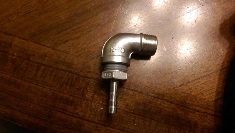
Now wrap the street elbow in Teflon tape and thread into the ball valve. Don't tighten it to the point that it will be aimed straight down as this will make it hard to put sample containers under it without hitting the tubing for the inlet below.
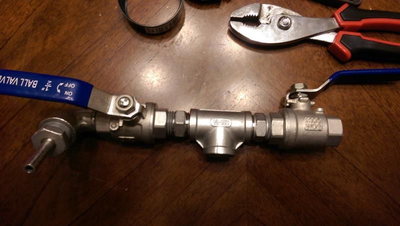
Next, wrap the outlet on the pump head with Teflon, and thread the Tee onto it until tight and the ball valves are running side to side, straight over the pump head.
At this point you will want to attach the fittings of your choice to the inlet and the outlet connectors for hooking up your tubing. Make sure to wrap the threads with Teflon.
At this point wrap the threaded part of the barb fitting with Teflon and thread into the street elbow.
Now wrap the street elbow in Teflon tape and thread into the ball valve. Don't tighten it to the point that it will be aimed straight down as this will make it hard to put sample containers under it without hitting the tubing for the inlet below.
Next, wrap the outlet on the pump head with Teflon, and thread the Tee onto it until tight and the ball valves are running side to side, straight over the pump head.
At this point you will want to attach the fittings of your choice to the inlet and the outlet connectors for hooking up your tubing. Make sure to wrap the threads with Teflon.
Align the pump head to the housing and attach it using the original screws.
Step 7:
To ensure that everything is in working order, plug in your pump, attach your inlet hosing to a water source (like your kettle) and allow the tubing to fill (never run a March Pump when dry). Turn on the switch and engage the magnetic drive. Open the venting ball valve and allow the air to escape from the head space in the pump head.
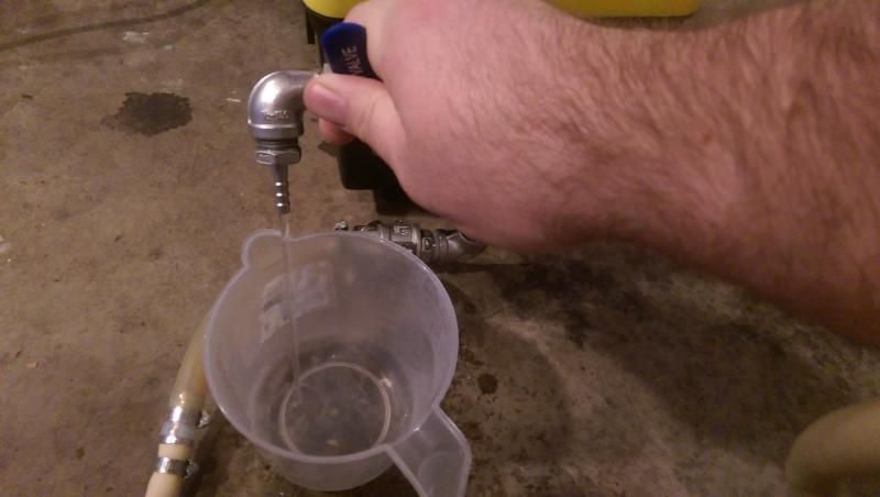
Once you have cleared the air, close the venting valve while opening the outlet (make sure you have your tubing attached). Make sure to have the end of your tubing aimed back into the water source so you can cycle it through. Ensure that there is no water on the ground pooling under the pump head, and feel all your points of connection for any small leaks. Once you know you are leak free, you can use it for brewing.

For my hosing I used a 1 foot section of 1/2" ID silicone tubing and attached a 4-5 foot length of Thermoplastic tubing to it using 1/2" Barb couplings. I did this for both the inlet and outlet tubes. This allows me to see the liquid in the tubing at the inlet (silicone) to ensure that I am not running it dry (thermoplastic tubing is completely opaque), and at the end of the outlet tubing to see if it is indeed flowing to the top of the tubing. For this I have the tubes set up so that the liquid is moving through the thermoplastic towards the silicone, then exiting the tube (either into the pump head inlet or out of the pump outlet tube). Each of my tubes have a Cam-Lock to barb on each end.
To ensure that everything is in working order, plug in your pump, attach your inlet hosing to a water source (like your kettle) and allow the tubing to fill (never run a March Pump when dry). Turn on the switch and engage the magnetic drive. Open the venting ball valve and allow the air to escape from the head space in the pump head.
Once you have cleared the air, close the venting valve while opening the outlet (make sure you have your tubing attached). Make sure to have the end of your tubing aimed back into the water source so you can cycle it through. Ensure that there is no water on the ground pooling under the pump head, and feel all your points of connection for any small leaks. Once you know you are leak free, you can use it for brewing.
For my hosing I used a 1 foot section of 1/2" ID silicone tubing and attached a 4-5 foot length of Thermoplastic tubing to it using 1/2" Barb couplings. I did this for both the inlet and outlet tubes. This allows me to see the liquid in the tubing at the inlet (silicone) to ensure that I am not running it dry (thermoplastic tubing is completely opaque), and at the end of the outlet tubing to see if it is indeed flowing to the top of the tubing. For this I have the tubes set up so that the liquid is moving through the thermoplastic towards the silicone, then exiting the tube (either into the pump head inlet or out of the pump outlet tube). Each of my tubes have a Cam-Lock to barb on each end.
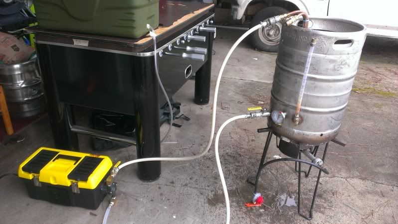
I also installed the cam lock fittings to my ball valves on my kettles, my Mash Tun ball valve, my Whirpool Arm on my Chiller, and also now on the top of my sight glass on my kettles. On brew day, I run off from the Mash Tun into a 1 gallon plastic container for my vorlauf. Once my runnings are clear, I hook the outlet tubing to the ball valve on my kettle and pump the wort in from the bottom to keep from splashing the hot wort. Once the boil is over I run the super hot wort through the pump and recirculate it through my whirpool arm which sanitizes the pump and tubing. I continue to do this as the wort chills causing a whirlpool in the kettle. I also use the pump to move the liquid from the kettle into my fermentor(s) in my fermentation fridge.
For cleaning, I can add hot Oxi-Clean water to my kettle, and then run it through the pump and back into the kettle through my sight glass which cleans the kettle ball valve, tubing, pump head, ball valves, and the sight glass using a recirc. This should be done every few months. I waited two years, just running hot water through the tubing after each brew day, and when I finally gave it a good Oxi recirc it came out of the tubing neon green (all the hop oils stuck to the tubing walls).
I really like the idea of the sample port!
ReplyDeleteYes, me too. My original pump set up from 2 years ago didn't have the dual outlet and I had issues getting the air out of the line. After reading the current BYO article on pump design and configuration I decided to add the tee and second valve for releasing air. It actually works great as a sample port too. After chilling I used to pull my sample from the end of my outlet tubing on its way to the fermentor. That could get messy as the cam lock fittings on my tubing have holes in them for the wings, and the wort would trickle out of them when taking my sample. No longer an issue now.
Delete